
3 Real, Reactive, and Active Power
DC Circuit
In a DC circuit, all the derivations of the power formula combined with ohms law can be used such as Power = V*I, Power = I2R, and Power = V2/R. The units of DC power are Watts [named after James Watt (1736-1819)]. DC power can be thought of as power consumed by a resistor.
AC Circuit
In an AC circuit power becomes much more complicated. In the US the AC power is generated for a 60 Hz, 120-volt standard. Hz means cycles per second. Hence 60 times a second a sine wave with a peak amplitude of approximately 170 volts is generated. This cycling sine wave in AC can create three types of power: 1) real power, 2) reactive power, and 3) apparent power.
- Real, Active, or Average Power is the power consumed by a resistor. It is denoted with a ‘P’. As in DC circuits, real power has units of watts. Only two power formulas can be used to calculate real power:
P = I2R or P = V2/R.
Examples
#1 Calculate the power consumed by a 1 kΩ resistor with 5 mA flowing through it.
P = I2R = (5mA)2*1kΩ = 25 mW
#2 Calculate the power consumed by a 1 kΩ resistor with a 15 volt drop across it.
P = V2/R = (15v)2/1 kΩ = 225 mW
Examples of electrical devices that only consume real power are electric stoves, hairdryers, electric water heaters, and toasters. - Reactive Power is the power that is consumed by inductors and capacitors. It is denoted with a ‘Q’. Reactive power has units of VAR (Volt-Amps Reactive). Hence, 60 times the second energy is stored and released in inductors and capacitors. The inductive reactance of pure inductors +jXL. This means that an inductor is +90 degrees out of phase with a resistor (which is at 0 degrees). The capacitive reactance of a pure capacitor -jXC. This means that a capacitor is -90 degrees out of phase with a resistor (which is at 0 degrees). The net reactance in a circuit is X = +jXL-jXC. Hence, the reactance will always be either net capacitive or net inductive. Only two power formulas can be used to calculate reactive power:
Q = I2X or Q = V2/X. If the net reactance is inductive Q is positive and if the net reactance is capacitive, Q is negative.
Examples
#1 Calculate the power consumed by a 2 kΩ inductive reactance with 4 mA flowing through it.
Q = I2R = (4mA)2*2kΩ = 32 mVAR
#2 Calculate the power consumed by a 1 kΩ inductor with a 15 volt drop across it.
P = V2/XL = (15v)2/1 kΩ = 225 mVAR
Examples of electrical devices that generate some reactive power are microwaves, washing machines, fans, and air conditioners. - Apparent Power is the hypotenuse of real and reactive power (see figure below). It is denoted with an ‘S’. Apparent power has units of VA (Volt-Amps). Apparent power is useful since it reveals the total current used by a combination of resistive, inductive, and capacitive components. Apparent Power = V*I. S = sqrt(R2 + Q2).
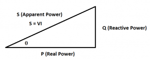
image by author - Power Factor
The power factor is defined to be Fp = cos Θ. Where Θ is the angle in the power triangle shown above (the angle between the Apparent Power and Real Power). If Fp = 1 (unity), then the real and apparent power are the same; hence, the reactive power would be zero. Ideally, utilities would like all consumers of electricity to just use only real power so that the power factor could remain in unity. Homes on average have a power factor of 0.95, restaurants 0.88, and industrial manufacturing 0.77 (Koutitas 15).
EXAMPLES
Here are some examplesIn the table below assuming a 120 V AC source and a RL = 5 Ohm for all inductorsValue Total Resistance = RL + R Impedance Rectangular Current Real Power Reactive Power Apparent Power Power Factor 1 μF + 47 mH f = 100 Hz
5 Ω 5 + j29 -j 1592 Ω = 5 -j1562 Ω 76.8 mA 29.5 mW -9.2 VAR 9.2 VA approximately 0 1 μF + 47 mH f = 1 kHz
5 Ω 5 + j295 -j 159 Ω = 5 +j139 Ω 863 mA 3.74 W +104 VAR 104 VA approximately 0 1 μF + 47 mH f = 10 kHz
5 Ω 5 + j2953 -j 16 Ω = 5 +j2938 Ω 40.8 mA 8.3 mW +4.9 VAR 4.9 VA approximately 0 300 Ω + 47 mH + 1μF f = 100 Hz
305 Ω 305 + j29 -j 1592 Ω = 305 -j1562 Ω 75.4 mA 1.73 W -8.88 VAR 9.04 VA 0.191 300 Ω + 47 mH + 1 μF f = 1 kHz
305 Ω 305 + j295 -j 159 Ω = 305 +j139 Ω 358 mA 39.1 W +17.8 VAR 43 VA 0.909 300 Ω + 47 mH + 1 μF f = 10 kHz
305 Ω 305 + j2953 -j 16 Ω = 305 +j2938 Ω 40.63 mA 503 mW +4.84 VAR 4.87 VA 0.1 3.3 k Ω + 22 nF + 470 mH f = 100 Hz 3305 Ω 3305 + j29 -j 1592 Ω = 3305 -j1562 Ω 32.83 mA 3.56 W -1.68 VAR 3.94 VA 0.904 3.3 k Ω + 22 nF + 470 mH f = 1 kHz 3305 Ω 3305 + j295 -j 159 Ω = 3305 +j139 Ω 36.3 mA 4.34 W +183 mVAR 4.34 VA approximately 1 3.3 k Ω + 22 nF + 470 mH f = 10 kHz 3305 Ω 3305 + j2953 -j 16 Ω = 3305 +j2938 Ω 27.13 mA 2.43 W +2.16 VAR 3.256VA 0.746 Do the attached worksheet https://kirkwood.pressbooks.pub/app/uploads/sites/13/2022/01/Real-Reactive-and-Apparent-Power-2.docx
Works Cited
Koutitas, George, and Stan McClellan. The Smart Grid As an Application Development Platform. Artech House, 2017.
